Wind Tunnel Build

This build is specifically designed to aid the lack of accessibility of tools and resources. Nevertheless, some effort is required to build the windtunnel we’ve optimised. The build is divided into two main components: the frame and the special components. The frame is the body of the windtunnel - the method for building which is common throughout the sections and is mentioned below. It starts with a blueprint anyone can print and ends with a sturdy frame ready to house your aerodynamic ideas. The special components include the honeycomb, power-pod, etc. Methods for these are different and are addressed appropriately below. Before that though, we build the frame.

Quick jump to section plans:

Wind Tunnel Frame - Build Plan

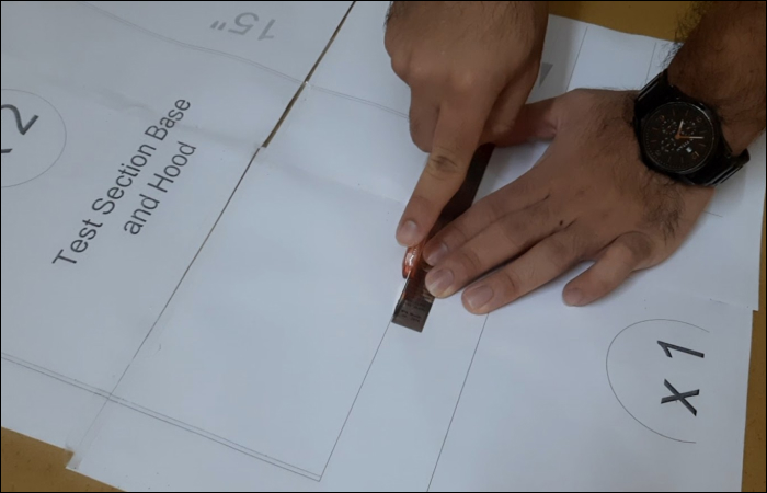
Building the frame is a fairly simple process. It starts with a printable blueprint plan, which you will use to trace and cut the components of the wind tunnel sections. The cardboard (or foamboard) pieces are joined together, which forms a the windtunnel. Besides this, only a few components remain to have a completely functional windtunnel.

Item Material Quantity
1 Cardboard
Wall - Single Wall Board
Flute Style - Corrugated
Thickness - 4.8mm (Flute A)
Paper - Kraft

4 sheets - 841 mm x 1188 mm (A0)
3 sheets - 594 mm x 841 mm (A1)
Total Required Area - 2375 sq. inches
2 Hot Glue Gun
Glue Stick
X 1
3 Thumb pins X 8
4 Exacto-Knife OR
Box Cutter
X 1
5 Metal Ruler/Scale (30 cm) X 1

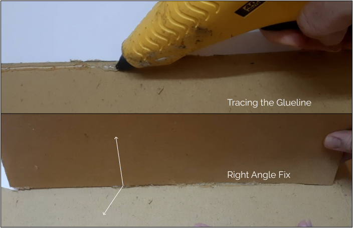
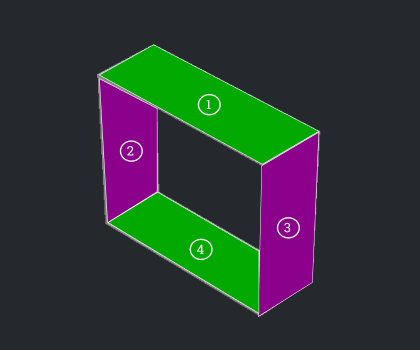
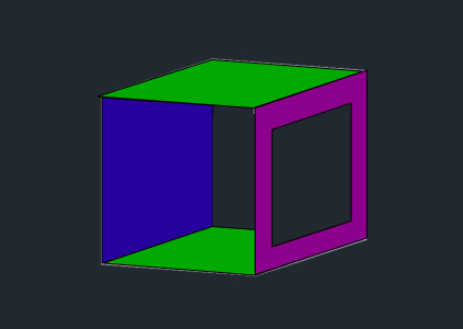
After cutting each of the section’s sides on the 2D board, we join them to form the 3D figure. Exactly like the adjacent image, where the 2D squares are cut and stuck at right angles from each other to form a 3D cube.

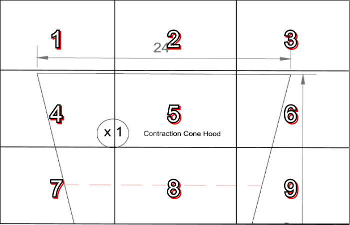
Now, the 2D shapes required to build the 3D sections of the windtunnel aren’t easy to make. This is why the full scale plans for each section are provided in the build plan below. Some of the dimensions of the pieces, however, are several inches larger and wider than the A4 sheet size, and only fit on A1 sheets.
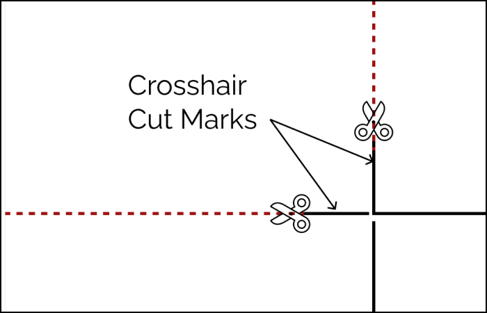
To make this accessible to everyone, though, the option of joining A4 sheets to stitch together the full-scale diagram is facilitated in the build plans.

The steps from printing to building all the section frames are common in procedure. They are as follows:

3D Cube from a 2D Board

Step #01 - View and Prepare Plan Sheet

  • Download and view the full scale plan of the section component you are building first. If you have the resources to plot/print the full scale non-tiled sheet, go ahead and print this file and head to Step #03.
  • If you cannot print this, go to the tiled scheme and print the entire document single-sidedly.

Step #02 - Layout Tiled Sheet

  • After printing the tiled document, arrange it like the layout you see in the cover page of the tiled plan. The numbers represent the page numbers of the tiled A4 sheets.
  • You will notice that there is some whitespace as you’re aligning them. Cut the sheet along its crosshairs on the corners and arrange them.
  • Once they’re arranged, stick the edges together with transparent plastic tape. This would stitch the tiles into the full scale sheet.

Step #03 - Place and Cut

  • Place the full scale sheet onto the cardboard/foamboard. Make sure the board’s length and breadth are large enough to accomodate the full sheet. If you weren’t able to scavenge a large enough sheet, you can use this method to make your board bigger.
  • Secure the sheet onto the board using thumb-pins and tape - make sure it doesn’t move. The Drawing Key at the corner of the page indicates the meaning of the diagram elements.
  • Carefully cut along the correct lines on the sheet. We recommend using a box-cutter and a ruler. The method is best depicted in this guide.

Step #04 - Join Cut-Out Pieces

  • Once you’ve cut all pieces for a section, join them together with hot glue. The best method is to apply an appropriate amount on the specified areas on the plan sheet - glueline.
  • Hold the piece at a right angle (90°) until the hot glue cools down.
  • Stick the sides to the base and then stick the hood to the sides. You will end up with a strong section frame for the wind tunnel.

Section Plans

Flow Stabilizer

Section(s) Color Key Plan Files
1, 4 - Hood & Base
2, 3 - Sides
Full Scale Plan (A0 Size) - Download
Tiled Plan (A4 Size) - Download
Special Components for the Flow Stabilizer - Tutorials:

Contraction Section

Section(s) Color Key Plan Files
1 - Hood
Full Scale Plan (A0 Size) - Download
Tiled Plan (A4 Size) - Download
2, 3 - Sides
Full Scale Plan (A0 Size) - Download
Tiled Plan (A4 Size) - Download
4 - Base
Full Scale Plan (A0 Size) - Download
Tiled Plan (A4 Size) - Download

Test Section

Section(s) Color Key Plan Files
1, 4 - Hood & Base
2 - Rear Side
3 - Observation Side
Full Scale Plan (A0 Size) - Download
Tiled Plan (A4 Size) - Download

Instruction
Stick a transparent OHP Sheet on the inner surface of the Observation Side of the Test Section. The sheet is secured with ordinary tape, around the edges of the hole cut out.

Diffuser

Section(s) Color Key Plan Files
1 - Hood
Full Scale Plan (A0 Size) - Download
Tiled Plan (A4 Size) - Download
2, 3 - Sides
4 - Base
Full Scale Plan (A0 Size) - Download
Tiled Plan (A4 Size) - Download
Power Pod - Construction Tutorial

Project Cost

The primary aim of this project was to make the windtunnel accessible to as many people as possible. The project is constantly working towards reducing costs, bettering designs, and optimising acccesibility parameters. As a result of that mission, today we stand at the figures mentioned below. We strive to continue getting better.

Component Groups Cost
Frame Section Components
Link to List
₹750 ($10)
Power-Pod Components
Link to List
₹2,002 ($26.70)
Total
~₹2,800 ($36.70)