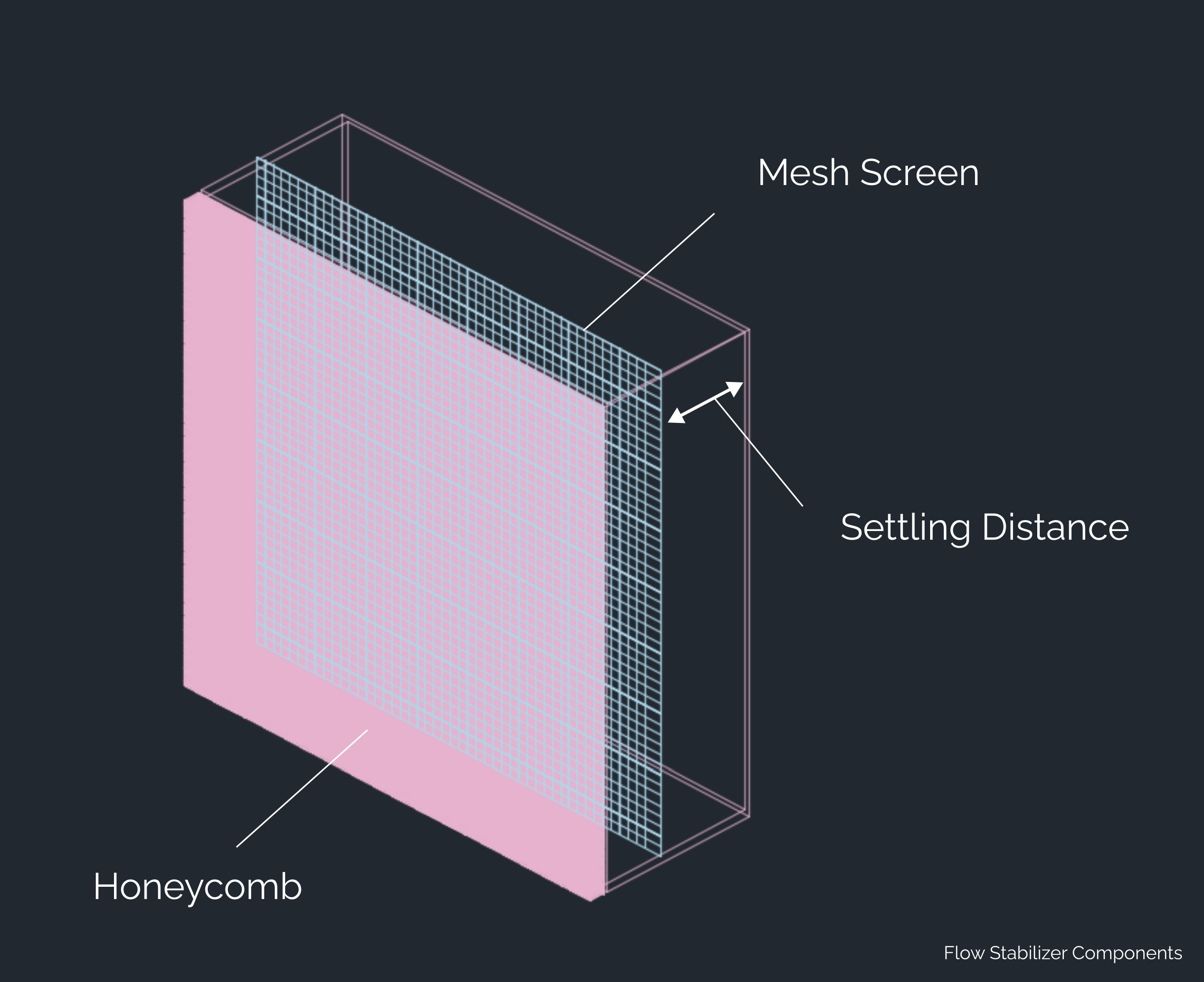
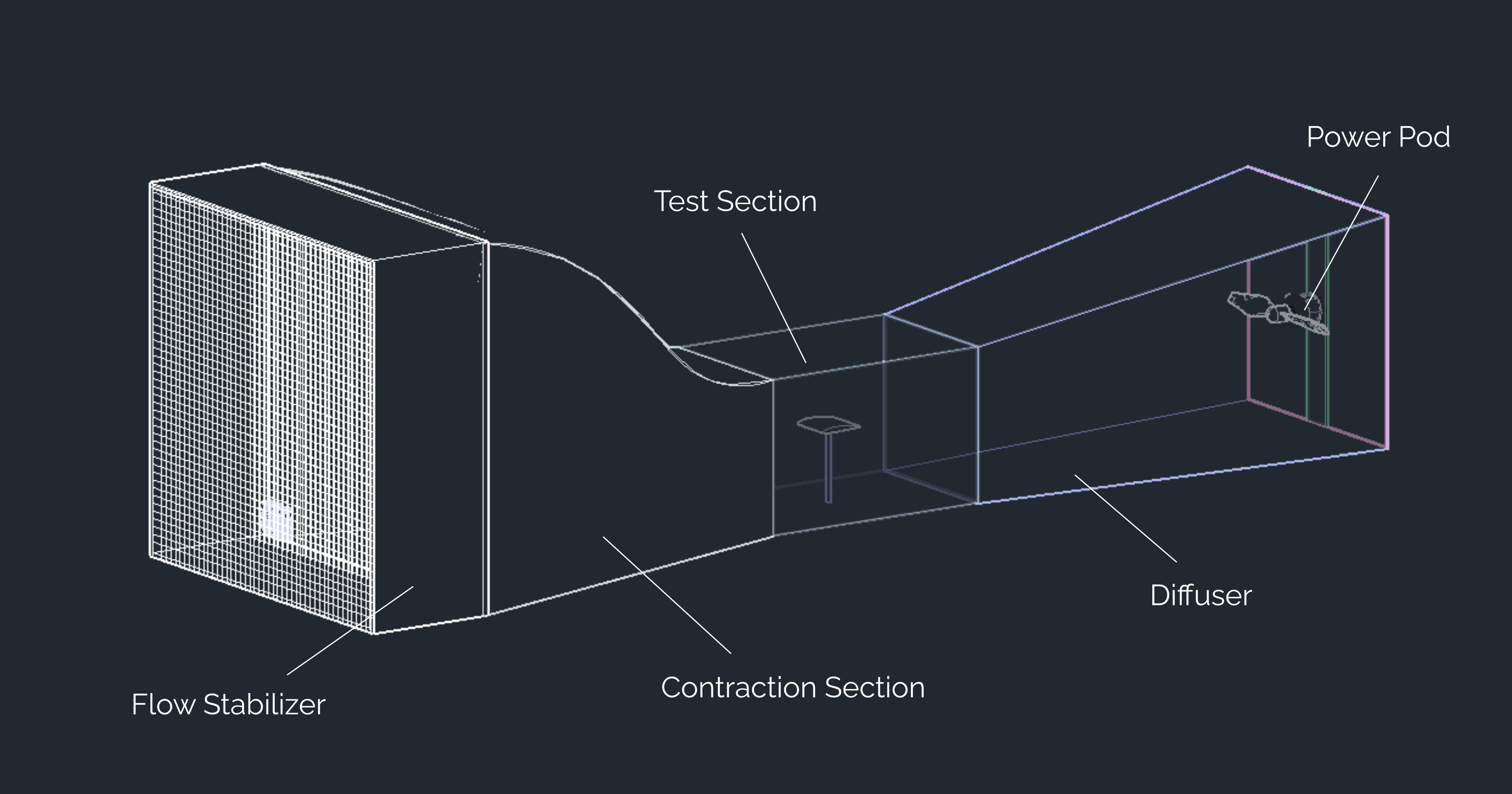
Wind Tunnel Components

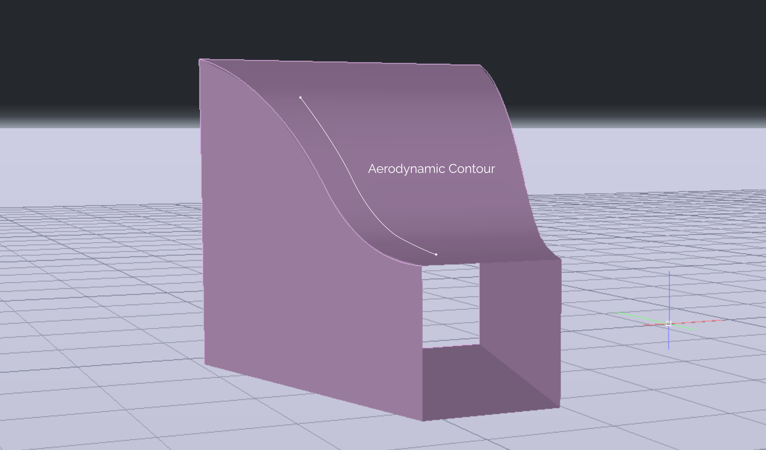
The purpose of windtunnels is to produce feasible circumstances for aerodynamic testing that are centered around the goal of producing reproducible conditions of turbulence-free airflow. Getting the cleanest possible airflow into the test section is the primary goal.
This innocent-seeming task poses immense obstacles with restrictions in each component of the apparatus. Furthermore, besides these intricate technical restrictions, there are many more non-technical.
This wind tunnel takes on the following general restrictions:

  • Build effort
  • Finances
  • Accessibility of material
This project, though, recognises the need to accomodate these restrictions and producing a solution with a unique design. In this document, we will discuss the design we've achieved after accouting for the aerodynamic properties each section fulfills. Their geometry, position, and other properties are carefully considered keeping in mind the other constraints of the project.

Research Backed Design

The dimensions, shapes, and placement of the windtunnel components are backed with relevant research that directly deals with the optimisation of windtunnels. You will find the explanation for each component in the sections below. Quick jumplinks:

Flow Stabilizer

Straightening Torroidal Airflow

The flow stabilizer is the first section of the wind tunnel and is responsible for channeling clean, laminar, and turbulence-free air into the remainder of the tunnel. It consists of one honeycomb, one mesh, and a settling distance. To reduce the amount of turbulence in the flow, Scheiman and Brooks [1] found that using a honeycomb with a screen produced better results than using a series of screens. A honeycomb with 2 or more screens did produce better flow, but unreasonably added to the boundary layer growth. A growing boundary layer sets the stage for flow separation and turbulence.
Therefore, this arrangement produces the best flow laminarity for the constraints in length and size of the section. Research-backed flow straightening is achieved in just 8.35 inches, an important optimisation for the overall length of the model.

Honeycomb

The honeycomb is generally the first component that the flow encounters in an open circuit suck-through tunnel. Its purpose is to reduce large scale turbulence in the flow and remove twist from the incoming air.
A honeycomb is made up of several cells of a minute diameter. While a hexagonal shape is recommended, ours will be circular since we’re using straws to pan out the availability of the project.
Bradshaw and Mehta [2] found that the minimum number of recommended cells is roughly 150 cells per inlet diameter: that is for the 24” length, we must fit 150 straws. The straw diameter of 40mm was found to fit this case. This happens to be the average diameter of a straw.
The 3 cm axial length yields a length to cell diameter ratio between 5 and 6 which is beneficial for low pressure losses and low turbulence generation.

Mesh Screen and Settling Distance

Screens increase the turbulence reduction through a combination of decreasing the scale of the turbulence and inducing small scale turbulence into the flow. Small scale turbulence interferes with large scale turbulence in the flow and aids in dissipating turbulence to heat faster. The mesh we’ll be using is subject to availability. Coming from a tropical region, mosquito meshes are a household commonality. Meshes in your grills, heaters, thermostat equipment can be used.

The mesh is attached at about 60mm from the honeycomb in the flow stabilizer upon the recommendation of Barlow et al. [3] that each screen has a spacing of 30 times the mesh size. In our case, the average household mesh has a diameter of 2mm. This yields 2mm x 30 = 60mm.

After the air passes through a screen, it turns turbulent for a small length until it stabilises. The air must be allowed to pass untouched for a distance known as the settling distance before it enters the next component - the contraction section. This length is given by Bradshaw and Mehta [2] who recommend a distance of 0.2 times the diameter of the opening.

Contraction Section

Directing Airflow into the Test Section

The contraction section takes steady flow from the wind tunnel’s inlet and brings it to the test section, the main observation component of the wind tunnel. The difference in cross sectional areas of the contraction section’s inlet and the outlet produces higher velocities at the outlet, which is the airflow required for the test section. Through conservation of mass this component smoothly brings the flow from a lower velocity to a higher velocity flow.

Fig 1.1

The principle of continuity is the main concept applied in this section of the windtunnel. In fig 1.1, v1’s magnitude is lower than v2’s. Since the same amount of mass is moving through A1 and A2 at the same time, particles ought to rush quicker through the narrower bit - exactly like placing a finger on a garden hose. Smaller area yields higher velocities.

Design Research

It is desirable to minimize the length of the contraction section as additional length increases boundary layer growth. However, if a high contraction ratio and angle is used over too short of a distance, flow separation will occur. In addition, high contraction ratios require more power from the wind tunnel fan. The ideal contraction ratio minimizing boundary layer growth and maximizing air velocity is between 6 and 9, as highlighted in Bradshaw and Pankhurst's paper [4]. The contour shape also aids the flow quality [5].

This makes the area of 576 square inches (24”x24”) yield a contraction ratio of 5.76:1, since the cross-sectional area of the test section is 100 square inches (10” x 10”). This ratio is close to the ideal recommendation. Furthermore, the dimension of 24” in the inlet of the contraction cone is the smallest possible size to accommodate 150 cell units in a single line for the honeycomb.

Test Section

Observation Area

The Test Section is the element that everything else in the wind-tunnel is built around. It is the component that houses the object subject to testing. All aerodynamic observations occur in this section.
To relieve the power dependencies on the motor, the length of the test section must be appropriately optimised.

According to Bradshaw and Mehta [2] the flow entering the test section will take 0.5 test section diameters. To allow for at least 10 inches of testing space, an optimised length of 15 inches was decided. A longer test section would again induce the broadening of the boundary layer and subsequently add the load to the motor in the diffuser.

This section holds the mount which is designed to be as aerodynamically invisible as possible, allowing us to view the interactions between the object intended only.

Diffuser

Pressure Recovery and Optimisation

The diffuser follows the test section and aids in smoothly transitioning the flow to the power pod, a step that is essential to optimise the testing velocity of the tunnel. Flow separation in the diffuser can cause pressure fluctuations and turbulence in the test section.

To optimise the pressure transition, a gradual angle from the test section to the outlet of the diffuser is essential. The flat-base design eliminates the need for a mount, greatly relieving the build effort. This allows for the base angle to be 0 degrees. The roof angle though must be large enough to allow a sufficiently large outlet, but cannot be so large that the pressure recovery is compromised. Bradshaw and Mehta [2] recommend that the best pressure recovery is achieved at 10 degrees.

The outlet dimension of 15 inches brings the area ratio close to the optimal 2.5:1 - 225 square inches diffuser outlet & a 100 square inches inlet from the test section - which also makes the diffuser’s length a desirable ~ 28 inches.
The dimensions and angles of the diffuser allow for a gradual pressure recovery without adding to the power load.

Power Pod

Finally, at the outlet of the diffuser sits the power pod. The power pod for this project is built from an r/c airplane motor and propeller. The conical nose spinner used to secure the prop to the motor is the best possible aerodynamic shape for the clean exit flow of the air passing through the tunnel.
The aerodynamic disturbances occuring from the fan itself is avoided in a suck-type-open circuit wind tunnel and is hence the chosen configuration.

References

[1] J. Scheiman and J. D. Brooks, "Comparison of Experimental and Theoretical Turbulence Reduction from Screens, Honeycomb, and Honeycomb-Screen Combinations," Journal of Aircraft, pp. 638-43, 1981.
[2] P. Bradshaw and R. D. Mehta, "Design Rules for Small Low Speed Wind Tunnels," The Aeronautical Journal of the Royal Aeronautical Society, pp. 443-49, 1979.
[3] Barlow, B. Jewel , W. H. Rae and A. Pope, Low-speed Wind Tunnel Testing, New York: Wiley, 1999.
[4] P. Bradshaw and R. Pankhurst, "The Design of Low-speed Wind Tunnels," Progress in Aerospace Sciences 5, pp. 1-69, 1964.
[5] T. Hahm and W. Steffen, "Turbulent Wakes in Wind Farm Configuration," T Ü V Nord, Systec Gmbh, Co Kg, Sciences, New York, 2006.